ST-NEHB100CN 4K60 HDMI/USB 2.0 HDBT Extender (100m)
ST-NEHB100CN 4K60 HDMI/USB 2.0 HDBT Extender (100m)
The 4K60 HDMI/USB 2.0 HDBT Extender can transmit HDMI high-definition
signal, bidirectional IR control signal, bidirectional RS-232 control signal and
USB 2.0 signal over CAT6 cable to the distance up to 328ft/100m (HBT mode)
or 492ft/150m (LRM mode). Video resolution is up to 4K2K@60Hz (4:4:4).
Transmitter supports audio embedding, and Receiver supports audio de
embedding. Audio pass-through is available when no video signal is trans
mitted. This product converts HDMI signal to standard HDBaseT signal and
transmits it through LAN cable. It can easily control signal source device or
display device from the remote end through bi-directional IR signal pass
through function. It supports EDID management (COPY TV/ Built-in) and
POC function with POC control switch.
The Extender can be widely used in other fields such as video conference
system, multimedia signal broadcasting, HDMI signal extension, etc.
Features
☆ HDMI 2.0b and HDCP 2.2/1.x compliant
☆ Support video resolution up to 4K2K@60Hz (4:4:4), 18Gbps video
bandwidth
☆ Up to 7.1 channels HD audio
☆ Built-in mode DIP switch for selecting the HBT mode or LRM mode
HBT mode: Audio and video signals can be transmitted up to 328ft/100m
for 4K60/4K30/1080P
LRM mode: Audio and video signals can be transmitted up to 492ft/150m
for 4K30/1080P
☆ Built-in EDID DIP switch supports intelligent EDID management
☆ Built-in audio DIP switch supports analog audio embedding
☆ Built-in POC switches, when both POC switches of TX and RX are turned
on, the Extender supports bidirectional 24V POC function, that is, either
TX or RX is powered by 24V1A power supply, the another does not need
power supply from the DC jack. (See the Description 1)
☆ Transmit bidirectional Infrared control signal together with the HDMI
signal. (See the Description 2)
IR IN is a 5V power supply level
☆ Transmit bidirectional RS-232 control signal together with the HDMI
signal. (See the Description 3)
☆ Supports USB 2.0 signal transmission
☆ Compact design for easy and flexible installation
Package Contents
① 1 x 4K60 HDMI/USB 2.0 HDBT Extender
② 1 x HDBT Receiver
③ 4 x 3pin-3.81mm Phoenix connector (male)
④ 1 x Wideband IR Receiver cable (1.5 meters)
⑤ 1 x IR Blaster cable (1.5 meters)
⑥ 4 x Mounting Ears
⑦ 8 x Machine Screws-M3*4
⑧ 1 x 24V/1A Locking Power Supply
⑨ 1 x User Manual
Specifications
| Technical | |
| HDMI Compliance | HDMI 2.0b |
| HDCP Compliance | HDCP 2.2 |
| Video Bandwidth | 18Gbps |
| Video Resolution | Up to 4K2K@60Hz 4:4:4 |
| Color Space | RGB 4:4:4, YCbCr 4:4:4, YCbCr 4:2:2, YCbCr 4:2:0 |
| Color Depth | 8/10/12-bit |
| HDMI Audio Formats | LPCM 7.1CH, Dolby TrueHD and DTS-HD Master (Full format) |
| ESD Protection | IEC 61000-4-2: ±8kV (Air-gap discharge) & ±4kV (Contact discharge) |
| Transmission | |
| STD-HBT Mode | 328ft / 100m (4K@60Hz / 4K@30Hz / 1080P) over CAT6 |
| LRM Mode | 492ft / 150m (4K@30Hz / 1080P) over CAT6 |
| Connection – Transmitter | |
| Input | 1× HDMI IN [Type A, 19-pin female] 1× AUDIO IN [3-pin 3.81mm Phoenix connector] |
| Output | 1× HDMI OUT [Type A, 19-pin female] 1× HDBT OUT [RJ45] |
| Control | 1× TO PC [USB Type B] 1× RS-232 [3-pin 3.81mm Phoenix connector] 1× IR IN [3.5mm Stereo Mini-jack] 1× IR OUT [3.5mm Stereo Mini-jack] 1× SERVICE [Micro USB] |
| Connection – Receiver | |
| Input | 1× HDBT IN [RJ45] |
| Output | 1× HDMI OUT [Type A, 19-pin female] 1× AUDIO OUT [3-pin 3.81mm Phoenix connector] |
| Control | 2× USB 2.0 [USB Type A] 1× RS-232 [3-pin 3.81mm Phoenix connector] 1× IR IN [3.5mm Stereo Mini-jack] 1× IR OUT [3.5mm Stereo Mini-jack] 1× SERVICE [Micro USB] |
| Power | |
| Power Supply | DC 24V/1A (supports bidirectional POC function) |
| Power Consumption | 11.76W (Max) |
| Mechanical | |
| Dimensions | 157.2mm [W] × 88mm [D] × 20mm [H] |
| Weight | Transmitter: 380g | Receiver: 377g |
| Housing | Metal Enclosure – Black |
| Environmental | |
| Operating Temperature | 0°C ~ 40°C / 32°F ~ 104°F |
| Storage Temperature | -20°C ~ 60°C / -4°F ~ 140°F |
| Relative Humidity | 20%~90% RH (non-condensing) |
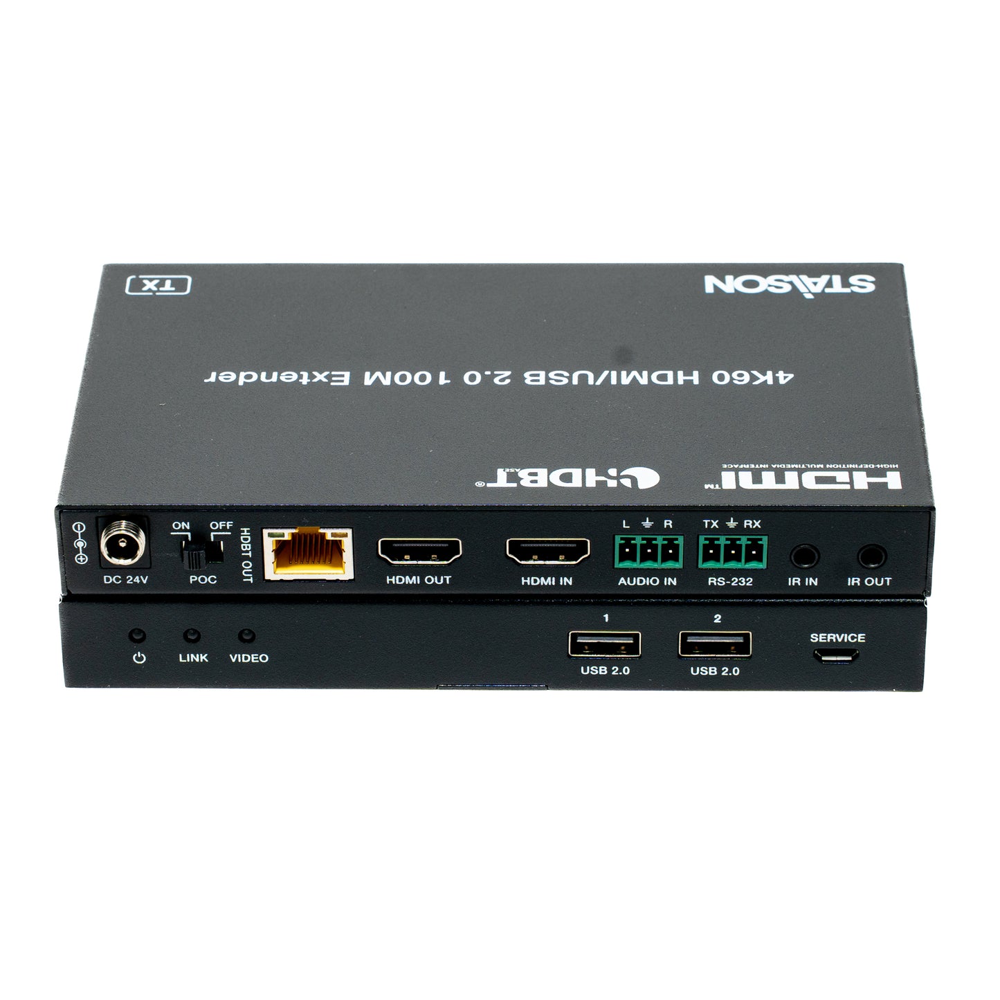
Operation Controls and Functions
Transmitter Panel

| No. | Name | Function Description |
|---|---|---|
| 1 | Power LED (Red) | Indicates the Transmitter is powered on. |
| 2 | LINK LED (Green) | Link status indicator: ▪ Light on: Transmitter and Receiver are in good connection status. ▪ Light Flashing: Transmitter and Receiver are in poor connection status. ▪ Light off: Transmitter and Receiver are not connected. |
| 3 | VIDEO LED (Green) | Signal indicator: ▪ Light Flashing: There is valid signal input. ▪ Light off: There is no signal or the signal is invalid. |
| 4 | MODE DIP Switch | Used to select the working mode: LRM-long reach mode: Extend the signal up to 492ft/150m through a single CAT6 network cable. STD-HBT mode: Extend the signal up to 328ft/100m through a single CAT6 network cable. |
| 5 | AUDIO IN DIP Switch | Used to select the signal source for the audio output of Receiver: HDMI: Output the de-embedded audio from the HDMI IN port of Transmitter. L/R: Output the analog audio embedded from the AUDIO IN port of Transmitter. |
| 6 | EDID DIP Switch | Used to set the EDID information: 00- Copy RX display’s EDID (as factory default) 01- 4K30 4:4:4 10- 1080p60 4:4:4 11- 1200p60 4:4:4 |
| 7 | TO PC Port | USB HOST port, connected to PC. |
| 8 | SERVICE Port | Software update port. Send command “s switch uart 0!” to switch MCU; send command “s switch uart 1!”to switch VALENS. |
| 9 | DC 24V Port | DC 24V/1A power input port. Note that the extender supports POC function, it means that either transmitter or receiver is powered on by 24V/1A power adapter, the other one doesn’t need power supply. |
| 10 | POC Switch | Use the switch to turn on/off POC function. |
| 11 | HDBT OUT Port | HDBaseT signal output port, connected to the HDBT IN port of Receiver with a CAT6 cable. |
| 12 | Link Signal Indicator (Green) | ▪ Light on: Transmitter and Receiver are in good connection status. ▪ Light Flashing: Transmitter and Receiver are in poor connection status. ▪ Light off: Transmitter and Receiver are not connected. |
| 13 | Data Signal Indicator (Yellow) | ▪ Light Flashing: There is data transmission. ▪ Light off: There is no data transmission. |
| 14 | HDMI OUT Port | HDMI loop output port, connected to HDMI display device such as TV or monitor. It loop output the audio and video signal of the HDMI IN port, and doesn't support audio embedding. |
| 15 | HDMI IN Port | HDMI signal input port, connected to HDMI source device, such as Blu-ray or PS4. |
| 16 | AUDIO IN Port | Analog audio input port for audio embedding. |
| 17 | RS-232 Port | Connected to PC or control system through 3-pin Phoenix connector for RS-232 serial command pass-through. |
| 18 | IR IN Port | Connected to IR wideband receiver cable, receiving the remote control signal and then send it to the receiving end. |
| 19 | IR OUT Port | Connected to IR blaster cable, sending the remote control signal from the receiving end. |
Receiver Panel

| No. | Name | Function Description |
|---|---|---|
| 1 | Power LED (Red) | Indicates the Receiver is powered on. |
| 2 | LINK LED (Green) | Link status indicator: ▪ Light on: Transmitter and Receiver are in good connection status. ▪ Light Flashing: Transmitter and Receiver are in poor connection status. ▪ Light off: Transmitter and Receiver are not connected. |
| 3 | VIDEO LED (Green) | Signal indicator: ▪ Light Flashing: There is valid signal input. ▪ Light off: There is no signal or the signal is invalid. |
| 4 | USB 2.0 Port | USB Type A ports for connecting USB 2.0 devices such as USB Flash Drive, Mouse and Keyboard. |
| 5 | SERVICE Port | Software update port. Send command “s switch uart 0!” to switch MCU; send command “s switch uart 1!”to switch VALENS. |
| 6 | DC 24V Port | DC 24V/1A power input port. Note that the extender supports POC function, it means that either transmitter or receiver is powered on by 24V/1A power adapter, the other one doesn’t need power supply. |
| 7 | POC Switch | Use the switch to turn on/off POC function. |
| 8 | HDBT IN Port | HDBaseT signal input port, connected to the HDBaseT OUT port of Transmitter with a CAT6 cable. |
| 9 | Link Signal Indicator (Green) |
▪ Light on: Transmitter and Receiver are in good connection status. ▪ Light Flashing: Transmitter and Receiver are in poor connection status. ▪ Light off: Transmitter and Receiver are not connected. |
| 10 | Data Signal Indicator (Yellow) |
▪ Light Flashing: There is data transmission. ▪ Light off: There is no data transmission. |
| 11 | HDMI OUT port |
HDMI signal output port, connected to HDMI display device such as TV or monitor. |
| 12 | AUDIO OUT port |
Analog audio output port. |
| 13 | RS-232 port | Connected to PC or control system through 3-pin Phoenix connector for RS-232 serial command pass-through. |
| 14 | IR IN port | Connected to IR wideband receiver cable, receiving the remote control signal and then send it to the transmitting end. |
| 15 | IR OUT port | Connected to IR blaster cable, sending the remote control signal from the transmitting end. |
IR Pin Definition
IR Receiver and Blaster pin’s definition is as below:

Note:
When the angle between the IR receiver and the remote control is ± 45 °, the transmission
distance is 0-5 meters;
When the angle between the IR receiver and the remote control is ± 90 °, the transmission
distance is 0-8 meters.
※ Description 1
POC (Power over Cable) Application Example

※ Description 2
Bidirectional Infrared control Application Example

※ Description 3
Bidirectional RS-232 control Application Example

Application Example

Product features
Product features
Materials and care
Materials and care
Merchandising tips
Merchandising tips