ST-NMXB42LMVUC 4x2 Seamless Matrix Switcher with Multiview and USB 3.2 Capture
ST-NMXB42LMVUC 4x2 Seamless Matrix Switcher with Multiview and USB 3.2 Capture
The 4x2 seamless matrix switcher supports video resolutions up to 4K@60Hz 4:4:4 8bit deep
color and HDCP 2.2 and 1.x compliant, it features multi-view function for multi sources can
be displayed on single screen. This matrix switcher supports two HDMI™ outputs and one
USB 3.2 capture output.
This matrix switcher features four HDMI™ inputs and each input with loop out port for
cascading connection. One local USB 3.2 host for UVC/UAC capture usage case.
This matrix switcher can be controlled via front panel buttons, remote control, API commands
using RS-232 or TCP/IP. A Web server / GUI is built in that features A/V control, and input
EDID management. The product is ideal for video conference rooms.
Features
☆ Video resolutions up to 4K@60Hz 4:4:4, as specified in HDMI™ 2.0b
☆ HDCP 2.2 and HDCP 1.x compliant
☆ USB 3.2 Gen 1 up to 5Gbps
☆ 4x2 seamless switching (single screen) and fast switching (multiview) function
☆ 4K video capture over USB 3.2 Gen 1 with standard UVC/UAC protocol
☆ Seamless switching without black screen or tearing screen (matrix mode)
☆ Multiple multiview display modes: Auto/Single/PIP/PBP/Triple/Quad view and customized
layouts
☆ Supports HDR10, HDR10+, HLG and Dolby Vision pass-through
☆ Supports HDR to SDR conversion
☆ Auto or manual switching mode
☆ Input: 4x HDMI™, 1x USB 3.2 Gen 1 host
☆ Output: 4x HDMI™ loop, 2x HDMI™, 1x Optical audio, 1x Analog audio
☆ Audio de-embedded
☆ Advanced EDID management
☆ Flexible control via front panel buttons, IR remote, RS-232, TCP/IP or Web GUI
Package Contents
① 1x 4x2 Seamless Matrix Switcher
② 1x IR Remote Control
③ 1x USB 3.0 Host Cable (USB-A to USB-B, 0.5m)
④ 1x IR Wideband Receiver Cable (1.5m)
⑤ 1x 3pin-3.5mm Phoenix Connector (male)
⑥ 1x 5pin-3.5mm Phoenix Connector (male)
⑦ 2x Mounting Ear
⑧ 8x Machine Screw
⑨ 1x Multinational AC Power Cord (1.5m, optional)
⑩ 1x User Manual
Specifications
| Technical | |
| HDMI Compliance | HDMI™ 2.0b |
| HDCP Compliance | HDCP 2.2 and 1.x |
| Video Bandwidth | 18Gbps |
| Input Video Resolution | 640x480p60Hz, 800x600p60Hz, 1024x768p60Hz, 1280x1024p60Hz, 1360x768p60Hz, 1440x900p60Hz, 1440x1050p60Hz, 1600x1200p60Hz, 720x480i59.94Hz (480i59), 720x480p59.94Hz (480p59), 720x576i50Hz (576i50), 720x576p50Hz (576p50), 1280x720p50Hz (720p50), 1280x720p59.94Hz (720p59), 1280x720p60Hz (720p60), 1920x1080i50Hz (1080i50), 1920x1080i59.94Hz (1080i59), 1920x1080i60Hz (1080i60), 1920x1080p23.98Hz (1080p23), 1920x1080p24Hz (1080p24), 1920x1080p25Hz (1080p25), 1920x1080p29.97Hz (1080p29), 1920x1080p30Hz (1080p30), 1920x1080p50Hz (1080p50), 1920x1080p59.94Hz (1080p59), 1920x1080p60Hz (1080p60), 3840x2160p23.98Hz (2160p23), 3840x2160p24Hz (2160p24), 3840x2160p25Hz (2160p25), 3840x2160p29.97Hz (2160p29), 3840x2160p30Hz (2160p30), 3840x2160p50Hz (2160p50), 3840x2160p59.94Hz (2160p59), 3840x2160p60Hz (2160p60), 4096x2160p23.98Hz, 4096x2160p24Hz, 4096x2160p25Hz, 4096x2160p29.97Hz, 4096x2160p30Hz, 4096x2160p50Hz, 4096x2160p59.94Hz, 4096x2160p60Hz |
| Output Video Resolution | HDR Bypass Mode: Video passthrough from input HDR to SDR Mode: 1024x768p60Hz, 1280x720p50Hz, 1280x720p60Hz, 1280x800p60Hz, 1360x768p60Hz, 1920x1200p60Hz, 1920x1080i50Hz (1080i50), 1920x1080i60Hz (1080i60), 1920x1080p50Hz (1080p50), 1920x1080p60Hz (1080p60), 3840x2160p25Hz (2160p25), 3840x2160p30Hz (2160p30), 3840x2160p50Hz (2160p50), 3840x2160p60Hz (2160p60), 4096x2160p50Hz, 4096x2160p60Hz |
| Color Space | RGB, YCbCr_4:4:4, YCbCr_4:2:2, YCbCr_4:2:0 |
| Color Depth | 8/10/12-bit |
| HDR | HDR, HDR10, HDR10+, Dolby Vision, HLG |
| Audio Formats | HDMI™ Passthrough: LPCM, Dolby Digital/Plus/EX, Dolby True HD, Dolby Atoms, DTS, DTS-HD, DTS-HD Master Audio, DTS-96/24, DTS High Res Audio Breakout: Optical Out: Up to LPCM/Dolby/DTS 5.1CH Line Out: Only LPCM 2CH (sample rate 32~192kHz) |
| IR Level | 12Vp-p |
| IR Frequency | Wideband 20K-60KHz |
| USB Bandwidth | USB 3.2 Gen 1 up to 5Gbps |
| LINE Analog Audio Out | |
| Dynamic Range | >90dB@0dBu, 1kHzA-weighted |
| Audio S/N Ratio | >90dB@0dBu, 1kHzA-weighted |
| Output Level (Maximum) | 8.2dBu (2Vrms) @ balanced audio 2.2dBu (1Vrms) @ unbalanced audio |
| Output Impedance | 600 Ohm balanced 300 Ohm unbalanced |
| Audio Output Delay | <1ms |
| Audio THD+N | <0.01% @ +4dBu, 1kHz |
| Frequency Response | 20Hz to 20kHz (-/+0.5dB) |
| Connection | |
| Input ports | 4x IN [HDMI™ Type A, 19-pin female] |
| Output ports | 1x OUT 1 [HDMI™ Type A, 19-pin female, single/multiview output] 1x OUT 2 [HDMI™ Type A, 19-pin female, single screen output] 4x LOOP [HDMI™ Type A, 19-pin female] 1x LINE AUDIO OUT [5pin-3.5mm phoenix connector] 1x OPTICAL AUDIO OUT [S/PDIF] 1x UVC/4K [9-pin USB Host Type B, USB 3.2 Gen 1 5Gbps, supporting UVC/UAC] |
| Control ports | 1x RS-232 [3pin-3.5mm phoenix connector, RS-232 API control] 1x LAN [RJ45 connector, TCP/IP and Web GUI] 1x SERVICE [USB-C with USB 2.0 only, 12-pin female, FW upgrade port] 1x IR EXT [3.5mm audio jack, IR IN 12V level] |
| ESD Protection | |
| ESD Protection | IEC 61000-4-2: ±8kV (Air-gap discharge), ±4kV (Contact discharge) |
| Transmission Distance | HDMI™ passive cable: 9.8ft/3m USB 3.2 Gen 1 5Gbps passive cable: 4.9ft/1.5m |
| Mechanical | |
| Housing | Front panel: Aluminum; Rear case: Metal Enclosure |
| Color | Black |
| Dimensions | 440mm [W] × 200mm [D] × 44mm [H] |
| Weight | 2.65kg |
| Power | |
| Power Supply | AC100 - 240V 50/60Hz |
| Power Consumption | 61.6W (Max) |
| Environmental | |
| Operating Temperature | 0°C ~ 40°C / 32°F ~ 104°F |
| Storage Temperature | -20°C ~ 60°C / -4°F ~ 140°F |
| Operating Humidity | 20%~80% (relative humidity, non-condensing) |
| Storage Humidity | 10%~90% (relative humidity, non-condensing) |
Operation Controls and Functions
Front Panel

| No. | Name | Function Description |
|---|---|---|
| 1 | LCD screen | 1.8-inch LCD panel, with 284*240 resolution and IPS (Intrusion Prevention System). After powering on, the LCD screen will display the current input/output channel mapping of the matrix by default. In addition, information such as EDID, output resolution, baud rate, and IP address can be displayed/set by pressing menu buttons. |
| 2 | IR window | IR signal receiving window, receiving the IR remote signal to control certain functions of the machine. |
| 3 | LCD screen operation buttons (Each black button with blue indicator light) |
MENU: Press the MENU button to enter the primary menu, with five primary items (INPUT SETTINGS/OUTPUT SETTINGS/AUDIO BREAKOUT/SETUP/FIRMWARE), which can view/set various functions of the matrix, including input EDID, output resolution/HDR/USB/mute/stream, audio source/mute, LCD ontime, baud rate, network configuration, reboot, reset and firmware version. UP: Press the UP button to select the previous item. DOWN: Press the DOWN button to select the next item. LEFT: Left directional operation button. RIGHT: Right directional operation button. ENTER: Press the ENTER button to confirm and take effect. Notes: • Pressing the MENU button will return to the previous menu. • In any level menu, it will return to the initial display screen if no operation goes on within 10 seconds. |
| 4 | Matrix operation buttons (Each black button with blue indicator light) |
IN 1/IN 2/IN 3/IN 4: Input channel selection buttons. OUT 1/OUT 2: Output channel selection buttons. PRESET: Press the PRESET button to recall the presets circularly. FUNC: Function button. OUT + IN: Firstly press the OUT 1/2 button to select the output channel, then press the IN 1/2/3/4 button to select the input channel to complete the matrix mapping. For example, "OUT 1 + IN 1" indicates switching the input 1 signal source to output 1. FUNC + IN: Switch the input source to all outputs. For example, "FUNC + IN 1" indicates switching the input 1 signal source to all output ports. FUNC + FUNC + IN 1: View the IP address. FUNC + FUNC + IN 2: View the baud rate of the serial port. FUNC + FUNC + IN 3: Turn on signal management mode. FUNC + FUNC + IN 4: Turn off signal management mode. Note: The quick information will disappear automatically after being displayed for 3 seconds. |
| 5 | POWER button (Black button with red button light) | Short press the POWER button to power on the unit, the button light is off. Press and hold the POWER button for 3 seconds, the unit will enter the standby mode, and the red button light is on. |
| 6 | LOCK button (Black button with blue button light) | Press and hold the LOCK button for 3 seconds to lock front panel buttons (except the power button), the blue button light is on; Press it again to unlock, and the button light is off. |
| 7 | SERVICE port | USB-C port with USB 2.0 only, used for firmware upgrade. |
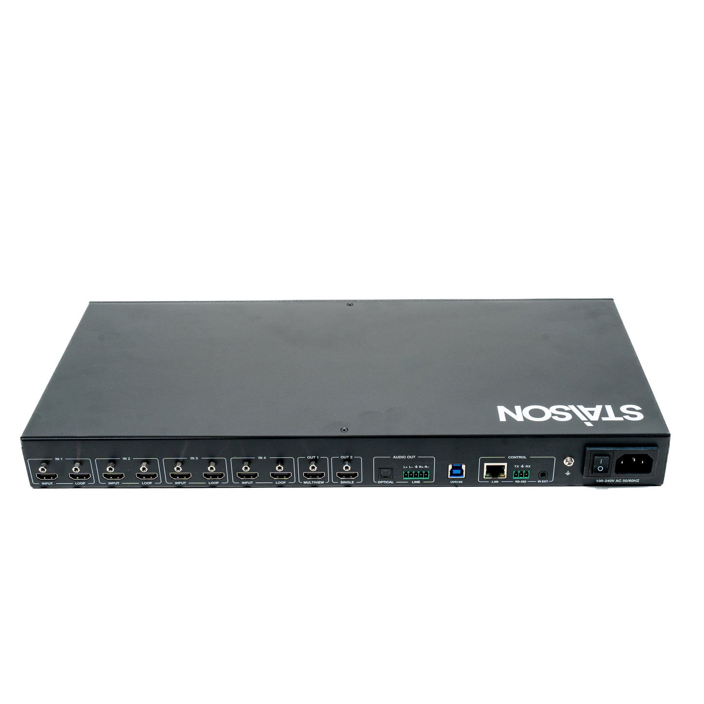
Rear Panel

| No. | Name | Function Description |
|---|---|---|
| 1 | IN 1/2/3/4 ports |
INPUT: Four HDMI signal input ports, supporting auto switching, connected to HDMI source devices such as DVD or Blu-ray player with HDMI cable. LOOP: Four HDMI signal loop output ports, supporting bypass and downscale, connected to HDMI display devices such as TV or monitor with HDMI cable. |
| 2 | MULTIVIEW OUT 1 port | HDMI signal output port, supporting single screen or multiview display. |
| 3 | SINGLE OUT 2 port | HDMI signal output port, only supporting single screen display. Besides, it supports HDR bypass, and HDR to SDR conversion. |
| 4 | OPTICAL port | Optical fiber audio output port, supporting audio de-embedding up to 5.1CH. |
| 5 | LINE port | Analog audio output port, supporting balanced/unbalanced 2CH audio output (with a maximum output level of 2Vrms). Balanced connection method: L+, L -, GND, R+, R- Unbalanced connection method: L+, GND, R+ |
| 6 | UVC/4K port | USB 3.2 Gen 1 capture port, supporting UVC/UAC. |
| 7 | LAN port | Ethernet port, used for TCP/IP and Web GUI control. • Green light on: The unit is linked with PC. • Green light off: The unit is not linked with PC. • Yellow light flashing: There is data transmission. • Yellow light off: There is no data transmission. |
| 8 | RS-232 port | RS-232 serial port, with baud rate of 115200, used for upgrade and API commands transmission. |
| 9 | IR EXT port | IR signal receiving port, with a default IR level of 12V, connected with the 12V IR Receiver cable. If the IR signal receiving window of the unit is blocked or the unit is installed in a closed area out of infrared line of sight, the IR receiver cable can be inserted to the "IR EXT" port to receive the IR remote signal. |
| 10 | GND | Connect the unit housing to the ground. |
| 11 | Power Switch | Press the power switch to turn on/off the power. |
| 12 | Power port | Universal AC power outlet, connected to the 100-240V AC 50/60Hz power supply. |
IR Cable Pin Assignment
The pin assignment of the IR Receiver cable and IR Blaster cable is as below:

| Pin | Assignment |
|---|---|
| 1 | IR Signal |
| 2 | Grounding |
| 3 | Power 12V |
Note: When the angle between the IR receiver and the remote control is ± 45°, the transmission distance is 0-5 meters; when the angle between the IR receiver and the remote control is ± 90°, the transmission distance is 0-8 meters.
IR Remote

① Power button: Press this button to power on the unit or set it to
standby mode.
② OUT 1 buttons:
IN 1/IN 2/IN 3/IN 4: Press to select input source for the OUT 1
port.
AUTO: Press this button to enable/disable the auto switching
function in single screen display mode.
: Press to circularly select the previous or next input source
for OUT 1 in single screen display mode, or for WIN 1 in
multiview display mode.
RES.: Press this button to cycle through the output resolution
for the OUT 1 port.
PIP: Press this button to switch output 1 to PIP display mode.
PBP: Press this button to switch output 1 to PBP display mode.
TRIPLE: Press this button to switch output 1 to Triple display mode.
QUAD: Press this button to switch output 1 to Quad display mode.
③ OUT 2 buttons:
IN 1/IN 2/IN 3/IN 4: Press to select input source for the OUT 2
port.
AUTO: Press this button to enable/disable the auto switching
function.
: Press to circularly select the previous or next input source
for the OUT 2 port.
RES.: Press this button to cycle through the output resolution for
the OUT 2 port.
④ Preset buttons:
PRESET 1/2/3/4/5/6/7/8: Press to recall the saved preset scenes.
The matrix switcher supports two methods to receive the IR remote control signal.
Method 1: The IR window receives the IR remote signal. When using the IR remote, the
furthest distance is 7 meters and the angle is ± 45°. The diagram is shown as below:

Method 2: If the IR receiver window of the matrix switcher is blocked or the matrix switcher is
installed in a closed area out of infrared line of sight, the IR receiver cable can be inserted to
the “IR EXT” port to receive the IR remote signal. The furthest distance of using the IR remote is
7 meters and the IR remote is directly faced to the IR receiver head. The diagram is shown as
below.

Multiview
The OUT 1 port of the matrix switcher supports multiple multiview display modes:
Auto: When the Auto mode is selected, the multiview display modes set through Web GUI
will be recalled automatically.
Single: Single screen display mode.
PBP: Dual screen display modes, including Dual-LR and Dual-TB.
PIP: PIP screen display modes, including PIP-LT, PIP-LB, PIP-RT and PIP-RB
Triple: Triple screen display modes, including Triple-L, Triple-R, Triple-T and Triple-B
Quad: Quad screen display modes, including Quad-L, Quad-R, Quad-T, Quad-B and Quad-S
Custom Layout: Five customized multiview display modes are supported.
Copy HDMI Out 2: Copy the display mode selected by the OUT 2 port.
Multiview window distributions are as following:

You can set/select multiview display modes for OUT 1 via Web GUI. For details, please refer
to the Video and System interface operation of “10. Web GUI Operation Guide”.
In addition, you can select multiview display modes for OUT 1 via IR remote control or
RS-232 commands.
Connection Diagram
1: General Application

2: Cascading Application

3: AV over IP Application

Product features
Product features
Materials and care
Materials and care
Merchandising tips
Merchandising tips