ST-NEB100AS-ENC SDVoE 4K60 over IP 10GbE Encoder & Decoder with Video Process and Zero Latency
ST-NEB100AS-ENC SDVoE 4K60 over IP 10GbE Encoder & Decoder with Video Process and Zero Latency
Regular price
0.00 SAR
Regular price
Sale price
0.00 SAR
ST-NEB100AS-ENC · VER 1.0
SDVoE 4K60 over IP 10GbE
Encoder & Decoder
Video Process & Zero Latency · BlueRiver AVP2000 · HDMI™ 2.0b · HDCP 2.2
1. Introduction
This product is an SDVoE-Compliant, All-In-One AV over IP solution providing highest-quality, uncompressed 4K60 and zero-frame latency audio/video extension over a standard 10G Fiber Network Switch. It transfers advanced HDMI™ content including HDR (high dynamic range), full color depth, and multi-channel HD Bitstream audio. Multiple control and data signals are transmitted simultaneously — including RS-232 and 1G Ethernet.
The 10G fiber port extends signals up to 40km via single-mode fiber, or 300m via multi-mode fiber. The 1G LAN port serves as a utility port for product management or Ethernet extension. The encoder supports HDMI™ loop out; the decoder HDMI™ output supports video scaling. Supports bi-directional analog stereo audio pass-through and RS-232 with 12V voltage output on connector.
Combining multiple encoders/decoders with one or more 10GbE fiber switches creates an ideal IP solution for distributed 4K60 video matrix, multiview, or video wall systems.
2. Features
3. Package Contents
📦 Encoder Package
1
SDVoE 4K60 over IP 10GbE Encoder1
4-pin 3.5mm Phoenix Connector1
12V/1A Locking Power Supply2
Mounting Ears4
Machine Screws (KM3×4)1
User Manual📦 Decoder Package
1
SDVoE 4K60 over IP 10GbE Decoder1
4-pin 3.5mm Phoenix Connector1
12V/1A Locking Power Supply2
Mounting Ears4
Machine Screws (KM3×4)1
User Manual
4. Specifications
| Parameter | Specification |
|---|---|
| Technical | |
| HDMI™ Compliance | HDMI™ 2.0b |
| HDCP Compliance | HDCP 2.2 |
| Video Bandwidth | 594MHz / 18Gbps |
| Video Compression Standard | SDVoE (Uncompressed) |
| Color Space | RGB, YCbCr 4:4:4 / 4:2:2, YUV 4:2:0 |
| Color Depth | 8/10/12-bit |
| HDR | HDR, HDR10, HDR10+, Dolby Vision, HLG |
| ESD Protection | IEC 61000-4-2: ±15kV (Air-gap discharge) & ±8kV (Contact discharge) |
| Video | |
| Input Video Resolution | 640×480p60 ~ 4096×2160p60 (full list includes 480i/p, 576i/p, 720p, 1080i/p, 2160p in various framerates up to 4096×2160p60Hz) |
| Output Video Resolution | Auto, 3840×2160p60/50/30/25, 4096×2160p60/50, 1920×1200p60RB, 1920×1080p60/50, 1360×768p60, 1280×800p60, 1280×720p60/50, 1024×768p60 |
| Video Latency | Zero latency |
| Audio | |
| Audio Formats | LPCM 2/5.1/7.1, Dolby Digital, Dolby Digital+, Dolby True HD, Dolby Atmos, DTS 5.1, DTS-HD Master Audio, DTS:X |
| Audio Latency | Zero latency |
| Audio Sample Rate | 22.05 / 24 / 32 / 44.1 / 48 / 88.2 / 96 / 176.4 / 192kHz |
| L/R IN/OUT Level | 1Vrms @ unbalanced audio |
| Input Impedance | 10K Ohms |
| Output Impedance | 330 Ohms |
| Frequency Response | +0.5dB / -0.5dB, 20Hz to 20kHz |
| Audio S/N Ratio | Line out: 88dB@0dBFS,1kHz A-weighted; Line in: 95dB@0dBFS,1kHz A-weighted |
| Audio THD+N | Line out: 0.036%@0dBFS,1kHz; Line in: 0.01%@0dBFS,1kHz |
| Audio Output Sync Delay | 0 to 50ms |
| Network | |
| Video Network Bandwidth | 10Gbps (SFP+) |
| Transmission Distance | Single-mode fiber: up to 40km Multi-mode fiber: up to 300m HDMI™ passive cable: 5m@4K60 / 10m@4K30 / 15m@1080p60 |
| Encoder Connections | |
| Input | 1× IN [HDMI™ Type A, 19-pin female] · 1× AUDIO IN [3.5mm jack] |
| Output | 1× SFP+ [Fiber, 10Gbps] · 1× OUT [HDMI™ Type A, 19-pin female] · 1× AUDIO OUT [3.5mm jack] |
| Control | 1× 1G LAN [RJ45] · 1× RS-232 [4-pin 3.5mm Phoenix connector] |
| Decoder Connections | |
| Input | 1× SFP+ [Fiber, 10Gbps] · 1× AUDIO IN [3.5mm jack] |
| Output | 1× OUT [HDMI™ Type A, 19-pin female] · 1× AUDIO OUT [3.5mm jack] |
| Control | 1× 1G LAN [RJ45] · 1× RS-232 [4-pin 3.5mm Phoenix connector] |
| Mechanical | |
| Housing | Metal Enclosure — Black |
| Dimensions | 95mm [W] × 120mm [D] × 21.5mm [H] |
| Weight | Encoder: 329g; Decoder: 323g |
| Power Supply | Input: AC100–240V 50/60Hz; Output: DC 12V/1A (US/EU, CE/FCC/UL certified) |
| Power Consumption (Max) | Encoder: 6.72W; Decoder: 6.36W |
| Environmental | |
| Operating Temperature | 0°C ~ 40°C / 32°F ~ 104°F |
| Storage Temperature | -20°C ~ 60°C / -4°F ~ 140°F |
| Operating Humidity | 20% ~ 80% RH (no condensation) |
| Storage Humidity | 10% ~ 90% RH (no condensation) |
5. Operation Controls and Functions
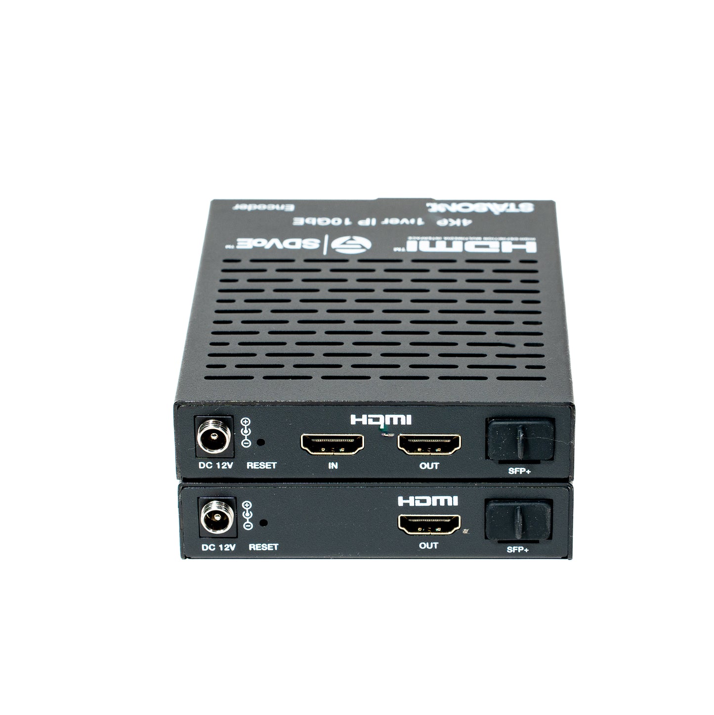
5.1 Encoder Panel
Encoder — Front & Rear Panels
| No. | Name | Function Description |
|---|---|---|
| 1 | POWER LED (Red) | On when unit is powered on. Off when powered off. |
| 2 | LINK LED (Yellow-green) | On: 10G network linked. Off: 10G network not linked. |
| 3 | VIDEO LED (Yellow-green) | On: Video signal detected on IN port and locked. Flashing: Video detected but cannot lock. |
| 4 | 1G LAN port | 1G network port — connect to 1G Ethernet or IP Controller. Link Signal (Green): on = cable connected normally. Data Signal (Yellow): flashing = data transmitting. |
| 5 | RS-232 port | Connect to PC or control system via 4-pin phoenix connector cable for configuration upgrade or RS-232 pass-through. Default baud rate: 57600. "12V" pin supplies power (100mA) to peripheral. |
| 6 | RS-232 (cont.) | See No. 5 above. The 4-pin block carries: 12V · TX · RX · GND. |
| 8 | AUDIO IN port | Analog audio input — for stereo analog audio pass-through and HDMI audio embedding. |
| 9 | AUDIO OUT port | Analog audio output — outputs HDMI extracted stereo audio or remote IP stereo audio stream. |
| 10 | DC 12V port | DC 12V/1A locking power input port. |
| 11 | RESET button | Press and hold 5 seconds (power on) — LINK and VIDEO LEDs flash at 1Hz simultaneously, then release to restore default settings. |
| 12 | IN port | HDMI signal input — connect to HDMI source device (Blu-ray Player, set-top box) with HDMI cable. |
| 13 | OUT port | HDMI local loop output — connect to an HDMI display device (TV, monitor). |
| 14 | SFP+ port | 10G fiber optical port — connect to 10G Switch for audio/video transmission. |
5.2 Decoder Panel
Decoder — Front & Rear Panels
| No. | Name | Function Description |
|---|---|---|
| 1 | POWER LED (Red) | On when unit is powered on. Off when powered off. |
| 2 | LINK LED (Yellow-green) | On: 10G network linked. Off: 10G network not linked. |
| 3 | VIDEO LED (Yellow-green) | On: Video signal detected and locked. Flashing: Video detected but cannot lock. |
| 4 | 1G LAN port | 1G network port — connect to 1G Ethernet or IP Controller. Link Signal (Green): on = cable connected. Data Signal (Yellow): flashing = data transmitting. |
| 5 | RS-232 port | Connect to PC or control system via 4-pin phoenix connector. Default baud rate: 57600. "12V" pin supplies power (100mA) to peripheral. |
| 6 | RS-232 (cont.) | 4-pin block carries: 12V · TX · RX · GND. |
| 8 | AUDIO IN port | Analog audio input — stereo analog audio pass-through and HDMI audio embedding. |
| 9 | AUDIO OUT port | Analog audio output — outputs HDMI extracted stereo audio or remote IP stereo audio stream. |
| 10 | DC 12V port | DC 12V/1A locking power input port. |
| 11 | RESET button | Press and hold 5 seconds (power on) — LINK and VIDEO LEDs flash at 1Hz simultaneously, then release to restore default settings. |
| 12 | OUT port | HDMI signal output — connect to HDMI display device (TV, monitor) with HDMI cable. |
| 13 | SFP+ port | 10G fiber optical port — connect to 10G Switch for audio/video transmission. |
6. Rack Mounting Instruction
⚠ Default IP Note The default IP mode of the SFP+ port is DHCP. If a DHCP server exists in the LAN, the IP is assigned automatically. If no DHCP server exists, the default IP will be 169.254.xxx.xxx with subnet mask 255.255.0.0.
6.1 Four-Unit (4U) Rack Mounting
1
Use the included screws to fix the two mounting ears onto the product (one on each side).
2
Insert the product with mounting ears into a 4U rack. Up to 12 units can be installed vertically in a standard 4U rack.
3
Use screws to fix the mounting ears to the rack rails to complete installation.
6.2 One-Unit (1U) Rack Mounting
1
Use included screws to fix two 1U rack panels on the product (one on each side).
2
Fix 1U rack panels on another three products the same way, then use screws to fix the 1U rack panels of two adjacent products together. Four units are installed per 1U rack space.
3
Fasten screws between the two 1U rack panels so that all four products are securely mounted together in the 1U rack.
7. Switch Model
The network switch used to set up the system must support all of the following features:
Recommended Switch Models:
| Manufacturer | Model Number |
|---|---|
| Netgear | ProSAFE PLUS XS708E |
| Netgear | ProSAFE Smart XS712T |
| Netgear | M7300-24XF XSM7224S |
| Netgear | ProSAFE M4300 Intelligent Edge Series |
| Arista Networks | 7050X Series |
8. SDVoE System Control
This product can be controlled by a Controller Box or a third-party controller. For full details of SDVoE system control, please refer to the SDVoE Controller Box user manual.
The Controller has two LAN ports: Video LAN (for AV network) and Control LAN (for management network). The recommended setup isolates the AV network from the control network for security. Connect Video LAN and all Encoders/Decoders to one switch; connect Control LAN and PC to another switch. Controls from the Control LAN via Web GUI/Telnet/SSH/API are bridged by the Controller.
For simple setups, all Encoders/Decoders, Video LAN, and PC can share a single network — the Control LAN port can remain unconnected (floating). Note: Only Control LAN connected while Video LAN is floating is not allowed.
💡 IP Configuration Notes Control LAN default mode: DHCP. Set PC to "Obtain IP automatically." If no DHCP server, the Controller Box Control LAN defaults to 192.168.6.100 — set PC to same subnet (e.g., 192.168.6.88). Access Web GUI at http://controller.local or http://192.168.6.100.
9. Application Example
SDVoE Full System — IP Matrix, MultiView, Video Wall & Point-to-Point
How it works: Multiple Encoders each accept a 4K60 source (Blu-ray, PC, TV Box, Media Player) and transmit uncompressed video via 10G SFP+ fiber to the central 10G Ethernet Switch. Decoders receive the stream from the switch and output to individual TVs. A MultiView decoder can display up to 25 source windows simultaneously, while a Video Wall configuration (4×DEC shown) tiles the image across multiple screens. The Controller Box manages routing, matrix switching, and system configuration via Web GUI or TCP/IP.
The terms HDMI, HDMI High-Definition Multimedia Interface, HDMI trade dress and the HDMI Logos are trademarks or registered trademarks of HDMI Licensing Administrator, Inc.
Product features
Product features
Materials and care
Materials and care
Merchandising tips
Merchandising tips